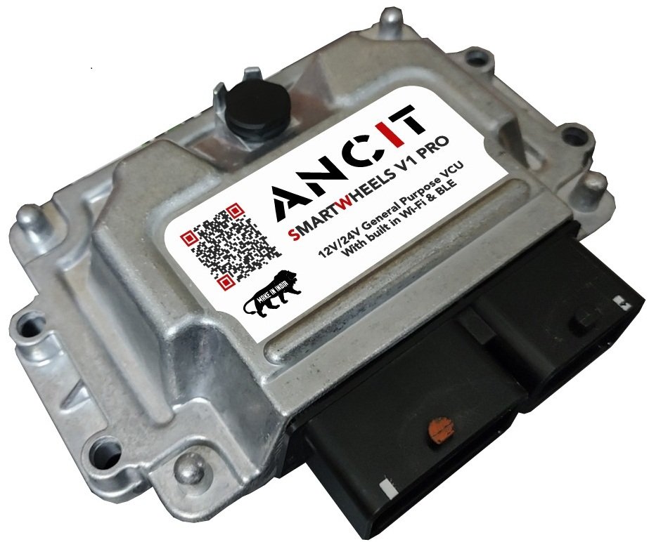
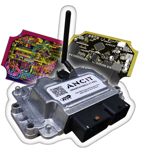
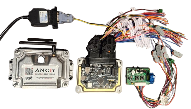
Smartwheels V1 Pro

Automotive ECU Platform

Smartwheels V1 Pro

ANCIT Smartwheels V1 Pro is a compact 80-pin automotive-grade ECU platform available in two powerful variants: NXP S32K144 and NXP S32K344. Both feature CAN, LIN, ADC, PWM, and GPIO interfaces, ideal for ECU prototyping, training, and integration of diagnostics, BMS, and vehicle control functions.

Two Hardware Variants
  • S32K144 – ARM Cortex-M4F, 80 MHz, ASIL-B
  • S32K344 – ARM Cortex-M7, 160 MHz, ASIL-D (EV & Hybrid Ready)
Applications
  • ECU design and testing
  • EV/Hybrid motor control & BMS
  • Telematics & OTA development
  • Advanced automotive education

Smartwheels V1 Pro bridges embedded control, connectivity, and diagnostics — ideal for OEM prototyping, Formula Bharat teams, and EduTech programs.

Choose Your Hardware Variant
NXP S32K144 – Entry-Level Automotive MCU

ARM Cortex-M4F @ 80 MHz | ASIL-B Compliant | Ideal for general ECU prototyping, training, and diagnostics

80-PIN ECU
CORE
Microcontroller NXP S32K144 (ARM Cortex-M4F, 80 MHz, 512KB Flash, 64KB RAM)
Power Supply Input: 10.8V - 36V (Automotive Grade)
COMMUNICATION INTERFACES
CAN & LIN Isolated CAN, Standard CAN, CAN FD (up to 5 Mbps), LIN
Wireless ESP32 C3 Mini (Wi-Fi & BLE), Optional 4G+GPS (Quectel EC200-UCNAA)
DIGITAL I/O
Digital Inputs 20x High-Speed Configurable (5V, 12V, 32V, VBAT) with frequency measurement
Digital Outputs
  • 4x High-Side Adjustable PWM (5V, 12V, VBAT)
  • 4x Low-Side PWM
  • 2x High-Side 4A PWM
  • 2x Low-Side 4A PWM
  • 1x H-Bridge 5A
ANALOG I/O
Analog Inputs 4x 0-10V, 4x 0-5V, 2x 4-20mA
Analog Outputs 2x 4-20mA
PERIPHERALS & DEBUG
Memory & Debug 64Mb Flash, 4KB EEPROM, Segger J-Link Debugger
Indicators Passive Buzzer, RGB LED
NXP S32K344 – High-Performance Automotive MCU

ARM Cortex-M7 @ 160 MHz | ASIL-D Ready | Ideal for EV/Hybrid motor control, BMS, and hydrogen fuel systems

80-PIN ECU
CORE
Microcontroller NXP S32K344 (ARM Cortex-M7, 160 MHz, ASIL-D Ready)
Power Supply Input: 7V – 28V, 30A Max
Reverse Polarity & Current Protection, Under Voltage Protection, 1000A TVS Surge Protection, Input Voltage & Current Monitoring
COMMUNICATION INTERFACES
CAN & LIN
  • 2x CAN FD (Up to 5 Mbps) – Non-Isolated
  • 1x CAN FD (Up to 1 Mbps) – Isolated
  • 1x RS232 (Up to 250 kbps)
  • 1x LIN / K-Line (Up to 20 kbps)
Wireless Onboard ESP32-C3 Wi-Fi & BLE, Future Ready OTA via Wi-Fi / BLE
DIGITAL I/O
Digital Inputs
  • 4x High Speed Digital Input (0–30V, 60kHz)
  • 1x KL15 Ignition Input
  • 1x Factory Reset Input (Bootloader Support)
Digital Outputs
  • 4x High Side Output – VBAT, 3A (5A Peak), 5kHz PWM
  • 2x Low Side Output – 5A (14A Peak), 20kHz PWM
  • 4x Adjustable High Side Output – 5V/12V/VBAT, 500–750mA
  • 4x Low Side Output – 500mA, 10kHz PWM
  • 4x H-Bridge Output – 4A per Channel
  • 12V/1A & 5V/1A Protected Outputs
ANALOG I/O
Analog Inputs
  • 13x Analog Input (0–5V)
  • 8x Precision Pull-Up Analog Input (Temp Sensors)
  • 4x 4–20mA Current Loop Input (2/3/4 Wire Supported)
PERIPHERALS & DEBUG
Memory & Debug 64 Mbit Flash, 4KB EEPROM, Onboard Segger J-Link Debugger
Debug Ports 10-Pin JTAG Debug Header, 10-Pin Trace32 Advanced Debug Port
Indicators RGB Diagnostic LED

Need help choosing the right variant? Contact us for expert guidance on your project requirements.

Get in Touch